


Please Leave Us A Message
Privacy statement: Your privacy is very important to Us. Our company promises not to disclose your personal information to any external company with out your explicit permission.

Jinan Longli Hydraulic Device Co.,Ltd
 September 28, 2018
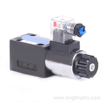
The Hydraulic Valve is an automation component operated with pressure oil. It is controlled by the pressure oil of the pressure distribution valve and is usually used in combination with an electromagnetic pressure distribution valve. It can be used to remotely control the on-off of oil, gas and water piping systems in hydropower stations. Commonly used for clamping, control, lubrication and other oil. There are direct-acting and pilot-type points, and many use pilot type.
Hydraulic valve
Components used to control fluid pressure, flow, and direction in hydraulic drives. The Pressure Control Valve is called a pressure control valve. The control flow is called a Flow Control Valve. The control of the opening, closing, and flow direction is called a Directional Control Valve.
Pressure control valve
Divided into use by the overflow valve, Pressure Reducing Valve and Sequence Valve . (1) Relief Valve : It can control the Hydraulic System to maintain a constant state when the set pressure is reached. Relief valves for overload protection are called safety valves. When the system fails and the pressure rises to a limit value that may cause damage, the valve port opens and overflows to ensure the safety of the system. (2) Pressure Reducing Valve: It can control the branch circuit to obtain a stable pressure lower than the main circuit oil pressure. Pressure reducing valve according to the pressure function it controls different, can be divided into fixed value pressure reducing valve (output pressure is a constant value), fixed pressure reducing valve (input and output pressure difference is a fixed value) and constant pressure reducing valve (Maintain a certain ratio between input and output pressure). (3) Sequence valve: After an actuator (such as hydraulic cylinder, hydraulic motor, etc.) can be operated, other actuators can be operated in sequence. The pressure generated by the oil pump first pushes the hydraulic cylinder 1 to move. At the same time, the oil inlet of the sequence valve acts on the area A. When the hydraulic cylinder 1 moves completely, the pressure increases, and the upward thrust acting on the area A is greater than the setting of the spring. After the value, the valve core rises so that the oil inlet and the oil outlet communicate and the hydraulic cylinder 2 moves.
Flow control valve
The flow rate is adjusted by adjusting the area of the orifice between the valve plug and the valve body and the local resistance generated by it to control the movement speed of the actuator. Flow control valves are divided into five types according to their use. (1) Throttle Valve : After setting the orifice area, the movement speed of the actuator, which can make the load pressure change little and the movement uniformity is not high, remains basically stable. (2) Speed control valve: It can maintain the differential pressure at the inlet and outlet of the throttle valve when the load pressure changes. In this way, after the throttle orifice area is set, regardless of how the load pressure changes, the speed control valve can maintain the flow through the throttle valve unchanged, so that the actuator movement speed is stable. (3) Diverter valve: Regardless of the size of the load, it is possible to use the same diverter valve or synchronizer valve to achieve equal flow of the two actuators of the same oil source; a proportional diverter valve is provided to distribute the flow proportionally. (4) Collector valve: In contrast to the diverter valve, the flow to the manifold is proportionally distributed. (5) Shunt manifold: It has two functions, diverter valve and manifold valve.
Directional control valve
According to the use, it is divided into one-way valve and reversing valve. One-way valve: only allow fluid in one-way connection in the pipeline, the reverse is cut off. Directional valve: change the on and off relationship between different pipelines, according to the number of working positions of the valve core in the valve body, two or three digits; according to the number of controlled channels, two, three, four, Five links, etc.; according to the spool drive manual, mobile, electric, hydraulic and so on. Figure 2 shows the working principle of the three-position four-way reversing valve. P is the oil supply port, O is the oil return port, and A and B are the output ports leading to the actuator. When the spool is in the neutral position, all ports are shut off and the actuator does not move; when the spool moves to the right position, P and A are open, B and O are open; when the spool moves to the left, P and B are Pass, A and O pass. In this way, the actuator can make positive and negative movements.
In the late 1960s, an electro-hydraulic Proportional Control Valve was developed on the basis of several hydraulic control valves mentioned above. Its output (pressure, flow) can continuously change with the input electrical signal. Electro-hydraulic proportional control valve according to different roles, corresponding to the electro-hydraulic proportional pressure control valve, electro-hydraulic proportional flow control valve and electro-hydraulic proportional directional control valve.
The above is the Know the Hydraulic Valve we have listed for you. You can submit the following form to obtain more industry information we provide for you.
You can visit our website or contact us, and we will provide the latest consultation and solutions
Send Inquiry
Most Popular
Related Products
Send Inquiry

Privacy statement: Your privacy is very important to Us. Our company promises not to disclose your personal information to any external company with out your explicit permission.
Fill in more information so that we can get in touch with you faster
Privacy statement: Your privacy is very important to Us. Our company promises not to disclose your personal information to any external company with out your explicit permission.